


When discharge distance is not reached on a cutter suction dredger (CSD), it’s rarely one “bad pump” or one unlucky day offshore. Most of the time, the whole transport system is drifting out of balance—pipeline losses, slurry velocity, pump duty point, wear, air leaks, or the way the line transitions from water to land.
This guide is for project managers, dredge masters, mechanical engineers, and site supervisors who need long distance dredging pumping to stay steady for weeks, not just for one good shift. We’ll break down ten common reasons a cutter suction dredger discharge distance falls short, how to confirm each one with field signals you already have, and what a practical fix plan looks like when the schedule is tight.
For a deeper, system-level explanation of pipeline friction, fittings, static head, and pump operating point, read our guide: why discharge distance is not reached in dredging projects.
Who this guide is for (and what “discharge distance” really means)
“Discharge distance” (often called pumping distance or transport distance) is the real, repeatable distance a dredging system can push slurry through a discharge line at a production rate that matters. It’s not the theoretical length of pipe you can connect on deck. It’s what you can actually run without the line sanding up, the discharge pressure bouncing, or the density collapsing the moment the cutter touches tougher ground.
In a CSD job, the production chain is simple on paper: cut, suck, pump, transport, discharge. In the field, that chain has dozens of small failure points. A few extra elbows, a slightly smaller pipe section, a half-closed valve, or a worn impeller can cut your usable distance hard.
When people say “we can’t reach the required discharge distance,” they usually mean one of these realities:
The slurry reaches land but the output collapses, so the reclamation area receives mostly water. Or the cutter pump hits a pressure ceiling and the crew is forced to lower density to keep the line moving. Or the pipeline plugs once per shift, and everyone starts blaming the soil.
That’s why troubleshooting needs to be system-level. It’s also why a solution often involves the discharge line itself—diameter, fittings, elevation profile, and sometimes a dredging booster pump station—as much as the main dredging pump.
A quick on-site diagnosis: what to look at in the first 10 minutes
Before changing anything, look at the job like an instrument technician.
Start with what the system is telling you right now: cutter pump discharge pressure, suction/vacuum stability, flow indication, density (if you have it), engine speed or drive speed, and the way those signals move when the cutter loads up. Even if your instrumentation isn’t perfect, trends matter. A stable system has stable patterns. A system that “won’t reach distance” usually shows unstable patterns—pressure spikes, density swings, or a slow drift down in head over days.
One of the most common mistakes in slurry pipeline pressure drop troubleshooting is chasing the wrong number. A single pressure gauge is not the truth; it’s one clue. In practice, two clues are much better: pressure at the pump discharge and pressure at a downstream point (a midline station, a shore manifold, or even a temporary test port). If downstream pressure is falling faster than discharge pressure is rising, losses in the line are growing. That’s not a pump problem. That’s a transport problem.
If your job is already tense and you need a “fast triage” mindset, ask three questions:
Are we losing head, losing velocity, or losing efficiency?
Is the loss steady (design mismatch) or sudden (fault, leak, blockage, cavitation)?
Does the problem show up only at high density/high production, or even at low density?
Those answers usually point to the right cause within one or two shifts.
The 10 most common reasons discharge distance is not reached (and how to fix each)
Reason #1: Dredging pipeline head loss is higher than assumed
On paper, the designer adds up the length, chooses a pipe diameter, estimates friction, and calls it a day. In the field, dredging pipeline head loss grows legs.
Losses climb when the pipeline has more fittings than expected, when route changes add elevation, when internal wear creates roughness, when the line has sand accumulation, or when a section gets swapped with a smaller inner diameter without anyone flagging it. The brutal truth: the pipeline is often the largest “hidden variable” in the job.
A real-world example: a line that runs fine at 2 km offshore suddenly struggles at 3.5 km after landfall routing is changed to avoid a temporary access road. The new route adds several tight turns and a short climb to clear a culvert. Nothing looks dramatic on a site map. But pressure rises and density drops. That’s classic “system head got bigger.”
Fixes usually start with the simplest: confirm actual pipe ID, confirm the number and type of bends, and confirm the route elevation profile. Then look for restrictions—partially closed valves, crushed hose sections, misaligned ball joints, or a line section that’s internally damaged.
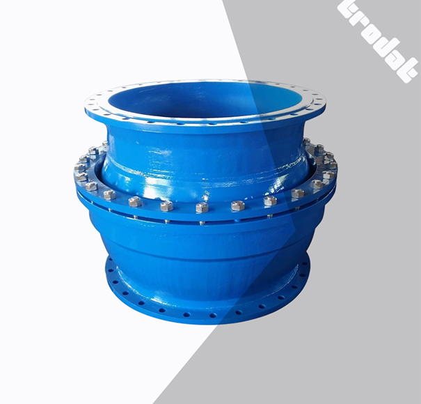
If your discharge line uses components like ball joints, discharge rubber hose, floating dredging hoses, and HDPE dredge pipe, remember each component has its own behavior and potential loss contribution depending on alignment and condition. TRODAT supplies these kinds of suction and discharge pipeline system components—HDPE dredge pipe, floating dredging hoses, discharge rubber hose, ball joints for mud drainage pipes, and floaters for dredging pipes—so the design intent is typically a balanced system rather than a pile of mismatched parts.
Reason #2: Slurry velocity drops below critical velocity, and the line starts to settle
A CSD discharge pipeline is a slurry transport system, not a water system. When velocity drops below the critical velocity slurry pipeline needs for your material, solids start to settle. Once settling begins, friction rises quickly, the effective pipe diameter shrinks, and you enter a feedback loop: higher loss reduces flow, lower flow increases settling, settling increases loss. That’s how a line that “kind of works” turns into a line that plugs at the worst moment.
This often shows up as a gradual loss of distance rather than an instant failure. The crew compensates by lowering density, which keeps the line moving but kills production and wastes fuel. The job “continues,” but the economics get ugly.
The fix is not always “add speed.” Sometimes it’s changing the operating window so the system stays in a stable transport regime. If the material suddenly becomes coarser sand or includes shell fragments, your safe operating window can shrink. You may need to reduce concentration temporarily, then rebuild velocity, then bring density back up. That sounds slow. In practice, it’s faster than clearing a plug twice a day.
Reason #3: The pump is operating off its curve, away from BEP
Even a solid dredging pump can’t give you distance if it’s running far from its best efficiency point. An operating point can drift when pipeline resistance changes, when suction conditions change, when impeller diameter is mismatched, or when speed control is crude.
If you see high discharge pressure but low effective flow, or you see power draw rising without matching production, you may be living off-curve. This matters because efficiency loss is not linear. Small deviations can be tolerated. Big deviations can make the pump feel “weak,” even if it’s mechanically fine.
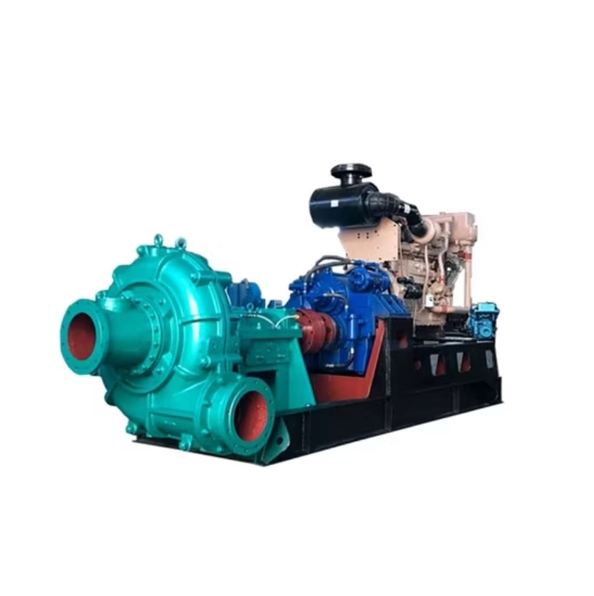
For CSD applications, TRODAT’s WN series dredging pump is described as a centrifugal dredging pump designed for suction and discharge of sediment, supporting high concentration transportation through impeller-driven negative pressure. In the field, that means you still need to match the pump and drive to the job’s head and flow requirement, not just pick a big pump and hope.
Reason #4: Wear is quietly stealing head and efficiency
Abrasive slurry eats performance. It doesn’t always fail loudly. More often, wear takes a few percent here and a few percent there—until the system no longer has margin.
The classic sign is “we used to reach this distance last month.” Same pipeline, same route, same material type. But now you need lower density to keep the line moving. That’s often wear in the impeller and liner opening up internal clearances, increasing recirculation, reducing effective head, and turning engine power into heat.
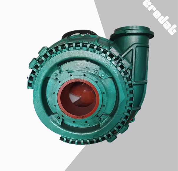
On dredging pumps, high chrome alloy impellers and liners are commonly used for wear resistance, and TRODAT lists high chrome alloy impeller and liner as part of the wear-resistant design for its WN series dredging pump. The point isn’t that wear disappears. The point is that wear rate and the predictability of wear can be managed with the right materials, maintenance intervals, and monitoring.
A practical approach is to treat discharge distance like a performance KPI. Track it. If the same production requires a higher pressure today than two weeks ago, your system is changing. That change is usually wear, buildup, or leaks.
Reason #5: Air ingress or suction-side leaks are reducing pump performance
Air leaks are sneaky. The system may still move slurry, but performance becomes unstable. Vacuum fluctuates, discharge pressure wanders, and production becomes sensitive to small changes in cutter load.
Suction-side leaks can come from gasket issues, worn seals, poorly seated connections, or damage at the suction line. In dredging, it doesn’t take a big hole. Small ingress over time can ruin stable operation, especially if it contributes to cavitation.
If you see foam in the discharge or you hear that “gravelly” sound that comes and goes, don’t assume it’s just material. Check for air ingress. Fixing one leak can give you more usable discharge distance than swapping a pump component.
Reason #6: Cavitation due to insufficient NPSH available
NPSH cavitation dredging pump issues often show up when a job pushes the limits—high speed, high suction lift, high temperature, or restricted suction piping.
Cavitation is not just noise. It’s performance loss and accelerated wear. When the pump cavitates, the effective head drops and the system loses discharge distance. The crew may respond by increasing speed. That can make cavitation worse. Now you’re burning the pump while still failing to reach distance.
A field-friendly way to think about it: if suction conditions are marginal, the system becomes fragile. A small change in tide, a small change in cutter depth, or a slightly higher slurry temperature can tip the pump into cavitation.
The fix is usually on the suction side: reduce suction losses, improve suction submergence, check for restrictions, and avoid operating points that demand more NPSH than the system can supply.
Reason #7: The job needs a booster pump station, but you’re trying to do it with one pump
Sometimes the system is simply underpowered for the required route. No amount of careful operation can change the physics of total head.
This is where a dredging booster pump station becomes less of an “upgrade” and more of a requirement. If the discharge line is long, includes landfall elevation, or must run through a complex route with multiple fittings and transitions, splitting the duty between the cutter pump and one or more booster pumps can stabilize velocity and production.
The biggest misunderstanding is thinking a booster is only for extending maximum distance. In many projects, it’s about stabilizing the operating window so you can keep density and velocity where they need to be. Without that stability, you spend the whole project compensating—lowering density, stopping for flushing, or clearing plugs.
TRODAT’s company profile lists “booster pump station” within its functional module offerings, alongside dredging pumps and hydraulic systems. That matters because a booster station is not only the pump; it’s also the integration—controls, piping, monitoring, and a start/stop philosophy that keeps the line safe.
Reason #8: Poor start-up, shutdown, and synchronization between pumps
Even with the right hardware, operations can sabotage discharge distance.
If pumps are started in the wrong sequence, the line can experience rapid pressure changes, flow reversals, or local settling. That can create deposits that make the next start harder. Over time, the “distance problem” becomes chronic.
A common field pattern is this: the line runs okay once fully stabilized, but each morning start is painful. That is often an operational sequencing issue combined with borderline velocity.
A more reliable approach is controlled ramp-up: stabilize flow first, then slowly increase density, while watching pressure stability. When a booster station is used, synchronization matters even more. Bad coordination can create pressure oscillations that stress the pipeline, especially around rubber hose sections and joints.
Reason #9: Pipeline routing and elevation profile are working against you
Pipeline routing is often decided by site constraints rather than pumping logic. That’s understandable. But every elevation climb costs head, and every complex transition increases losses.
Landfall is frequently the worst zone. Offshore, the line may be mostly level. Onshore, it may climb, zigzag, and cross obstacles. A short climb can consume more head than hundreds of meters of level pipe. If the elevation profile changed since the design estimate, your distance estimate is wrong, even if the pipe length is the same.
Using appropriate combinations of floating dredging hoses, floaters, HDPE pipe, and flexible hose sections is part of building a line that survives the site while keeping losses manageable. TRODAT’s suction and discharge pipeline system category includes these components, which are typically selected based on the project’s route and operating environment.
Reason #10: Material properties are different than expected—and the system isn’t tuned for it
You can pump fine sand a long way. You can pump clay too, but it behaves differently. Mix them, add shells, and the job becomes more complex.
If the project moves into coarser material or a higher solids content zone, the pipeline resistance can increase sharply. This is where “it used to work” becomes “it suddenly doesn’t,” even though nothing broke.
The fix is rarely a single knob. It’s usually a short cycle of adjustment: check particle size and density trends, adjust cutter and suction parameters, stabilize velocity, and keep the transport regime stable. If the new material is consistently tougher to pump, re-check pipe diameter and total head demand. Sometimes the right answer is acknowledging the design basis changed and adjusting the pumping system accordingly.
A systematic optimization plan that works on real projects
You don’t need a full simulation model to get a big improvement. You need a disciplined sequence.
Step 1: Establish a baseline you can trust
Pick one “standard condition” shift—same cutter depth range, same general material zone, stable sea state—and record your operating envelope. Capture discharge pressure, suction stability, approximate flow, density, speed, and production method used on site (even if it’s a rough estimate).
The goal is not perfect data. The goal is comparable data.
Step 2: Identify whether the bottleneck is head, velocity, or efficiency
If discharge pressure is near limit and flow is low, you’re head-limited.
If pressure is moderate but the line sands up, you’re velocity-limited.
If power is high but production is weak, you’re efficiency-limited, often due to wear or off-curve operation.
That classification tells you where to act first.
Step 3: Fix low-cost issues before touching equipment
Start with the obvious transport penalties: restrictions, route mistakes, valve positions, damaged hose sections, joint misalignment, and air leaks. These issues are common and cheap to fix compared with changing the pumping system.
If your job uses modular discharge components—rubber hose sections, ball joints, and HDPE pipe—inspect transitions carefully. A misaligned joint or a partly collapsed hose can create a localized loss that acts like a throttle.
Step 4: Bring the pump back to a healthy operating window
Once the line is “honest,” you can evaluate the pump. If wear is present, address it. If speed control is available, use it to keep the pump in a stable zone rather than constantly running at extremes.
TRODAT notes that its WN series dredging pump can be supplied with optional integrated frequency conversion speed control and real-time monitoring for stable operation and energy consumption management. Even if your system uses different control architecture, the operating concept is the same: smooth control beats constant chasing.
Step 5: Decide if a booster station is required—and design it as a system
If the project’s required total head exceeds what the cutter pump can provide with margin, don’t treat it like a crew problem. Treat it like an engineering problem.
In practice, adding a booster station becomes a decision about more than distance. It becomes a decision about stability, plug risk, and project schedule.
How to estimate whether you need a booster pump station (conceptual, field-friendly)
A conceptual method helps you make a rational decision without drowning in equations.
Think of total head demand as four buckets:
Static head: elevation changes.
Friction head: line length and internal roughness.
Local losses: bends, valves, reducers, entries/exits, and transitions.
Slurry effect: density, particle size, and how close you are to settling.
If the total head demand at your target production is close to the pump’s maximum sustainable head, you are living without margin. You might reach distance in perfect conditions, but you won’t reach it reliably across tides, materials, and wear.
A booster station is usually justified when you need to keep velocity safely above the settling threshold while maintaining production. It’s less about “one more kilometer” and more about keeping the whole line in the non-settling regime without abusing the cutter pump.
Common field mistakes that quietly kill discharge distance
The most expensive mistakes are the ones people normalize.
Running at low velocity “just to keep it moving” invites buildup, then future plugs. Ignoring early wear signals turns a manageable decline into a sudden failure. Treating air leaks as “minor” can keep the system unstable for months. Changing the pipeline route without revisiting the pumping basis can make every shift harder for no obvious reason.
And perhaps the most common mistake: chasing short-term output while damaging long-term stability. A CSD transport system pays you back when it’s stable. It punishes you when it’s pushed into unstable zones.
TRODAT (SHANDONG) MARINE ENGINEERING CO., LTD: a brief introduction
TRODAT (SHANDONG) MARINE ENGINEERING CO., LTD works as a supplier and integrator for dredging equipment and marine engineering components, supporting both newbuild dredgers and repair/maintenance needs. Its product range includes power and drive items such as dredging pumps, diesel engines, marine gearboxes, transfer cases, and hydraulic pump stations, as well as working devices like cutter heads and other dredging tools. TRODAT also supplies deck machinery and outfitting, and can provide specialized systems such as sediment production measurement and navigation solutions as customized requirements.
From a quality and compliance standpoint, the company states production follows ISO9001:2015 quality management, and IACS product certification can be provided for marine use.
Conclusion
When a cutter suction dredger can’t reach the required discharge distance, the fastest path to recovery is to stop guessing and treat the system as a chain: pump capability, suction condition, wear state, pipeline losses, route elevation, and slurry transport regime. Most projects don’t need a dramatic overhaul. They need disciplined diagnosis, a few targeted fixes, and—when physics demands it—a properly designed booster station and discharge pipeline system that can keep velocity and head where they belong. Done right, you don’t just gain distance. You gain stability, predictable production, and fewer “mystery” shutdowns.
FAQs
Why is my cutter suction dredger not reaching the required discharge distance?
In most cases, the system’s total head demand is higher than the pump system can deliver at a stable operating point. That increase often comes from dredging pipeline head loss (extra fittings, route changes, buildup), slurry velocity falling below the critical velocity, pump wear reducing head, or suction-side air leaks that destabilize performance.
What is the most common reason discharge distance is not reached in dredging projects?
A very common root cause is underestimated pipeline losses—especially when the discharge line has more bends, valves, transitions, or elevation climbs than the original plan. Once dredging pipeline head loss increases, the pump runs off-curve, production drops, and operators may lower density to keep flow, which further reduces effective output.
How do I know if I need a dredging booster pump station for long distance pumping?
You usually need a dredging booster pump station when the required total head at your target production exceeds what the cutter pump can provide with usable margin, especially after accounting for wear and changing material. If you can only keep the line moving by lowering density or accepting frequent plugs, that’s a strong operational sign the system is underpowered for long distance dredging pumping.
What slurry velocity should I maintain to prevent pipeline blockage on long discharge lines?
You need to keep slurry velocity above the critical velocity for your material so solids stay suspended and don’t settle. The exact value depends on pipe diameter, particle size, density, and concentration, but the practical clue is this: if velocity drops and the line starts sanding up, head loss rises quickly and discharge distance will shrink shift by shift.
Why does my discharge distance get worse over time even with the same pipeline length?
Gradual decline usually points to wear or transport changes, not “bad luck.” Pump wear can reduce head and efficiency, internal buildup increases friction, and small air leaks can make operation unstable. Over weeks, those small effects stack up until discharge distance is not reached unless you change operating conditions or restore system margin.
Post Comment