


On dredging jobsites, dredging pipeline system design is often what decides whether production holds steady or turns into repeated stoppages. A suction and discharge pipeline system that looks fine during early trials can begin to struggle once slurry density swings, discharge routes get extended, and the line has to stay stable through a full shift. The symptoms are familiar to contractors, project managers, and procurement teams: discharge distance falls short, pressure climbs without a matching flow gain, solids start to settle in low points, and small leaks at connections turn into hourly interruptions.
This guide focuses on practical, field-minded slurry pipeline design. It explains why systems fail, how to choose between hose and pipe by segment, how to manage floating dredging pipeline behavior in real water, and how to build a commissioning approach that reduces week-three surprises.
Why Pipeline Performance Breaks Down After the First Successful Runs
A common misconception is that pipeline trouble is “bad luck” or a single weak component. In reality, most production loss is predictable once the job moves beyond initial conditions.
Early runs often move lighter material with fewer abrupt changes in solids. Later, the dredge reaches different layers, particle size distribution shifts, and fines can change slurry behavior in ways that raise friction loss. At the same time, the discharge route rarely stays constant. A longer line, extra bends, a shoreline transition, or a temporary reroute can add local losses that were never captured in the first pipeline head loss calculation.
Even when the pump can provide the required head, pipeline losses can consume it faster than expected. That is how teams end up with a line that “should” reach the placement area but cannot maintain stable slurry velocity in practice.
Define the Jobsite Envelope Before Choosing Hose or Pipe
A strong slurry pipeline design starts with jobsite boundaries that can be defended in a quote request. The minimum set of inputs is straightforward: expected distance, elevation changes, routing constraints, and the range of slurry concentration and particle behavior over time.
In production reality, the key variable is not the average slurry density. It is the swing range. A system that works at moderate density may become unstable when density rises and the pipeline approaches a settling threshold. The same line can also show a different pressure profile when temperature changes stiffness in hoses, or when wave motion adds cyclic bending into a floating run.
The best practice is to design around a normal operating window, then sanity-check the worst-case band that tends to appear at the most inconvenient time: near schedule pressure, after a weather change, or when the dredge reaches a tougher layer.
Critical Slurry Velocity and the Two-Constraint Problem
Every dredging contractor has seen the same dilemma. Velocity that is too low invites settling. Velocity that is too high accelerates abrasion, especially at elbows, reducers, and transitions where turbulence concentrates.
That is why the “critical slurry velocity” concept matters beyond theory. When velocity falls below the point where solids stay suspended, settling begins in predictable locations: low spots, long horizontal sections with reduced energy, and the downstream side of bends. Once a bed forms, head loss increases, flow drops further, and the system can enter a loop that ends in a plug.
Design work should treat “no settling” as a constraint, but not the only one. Wear is the second constraint. An effective design aims for a transport velocity that resists settling while keeping the wear rate within a manageable maintenance plan.
Head Loss in Plain Language: Why Field Results Miss Calculations
Engineers know the components of total dynamic head. Field teams live with the consequences when the estimate is off.
Friction loss increases with velocity, but slurry adds complexity because its effective behavior changes with concentration and particle content. Local losses also accumulate quickly when routing is improvised. A few additional bends, an undersized reducer, or an extra valve for “convenience” can become permanent head consumers.
The practical takeaway is that pipeline head loss calculation should be treated as a living model. It should be checked against early measurements, then updated when the route changes. When a job expands its discharge distance, it is safer to reassess the system than to push the line harder and accept rapid wear.
HDPE Pipe vs Rubber Hose: Choose by Segment, Not by Preference
The most reliable systems rarely rely on a single conveyance type from end to end. Instead, they match each section to the risk profile of that section.
HDPE Dredging Pipe for Stable Long Runs
HDPE dredging pipe is commonly used where alignment can be controlled and where low corrosion exposure and long service life are procurement priorities. Product specifications for dredging-grade HDPE commonly emphasize corrosion resistance, impact resistance, crack growth resistance, low density for handling, and a smooth inner wall that supports transport efficiency. Under normal conditions, long service life is often cited as a design intent for this material class.
In practice, HDPE is strongest when the route is stable and the connection strategy is engineered. If the line must cross areas with frequent movement or high wave action, a rigid section can transmit stress into joints unless the transition is designed correctly.
Discharge Rubber Hose for Flex and Vibration Tolerance
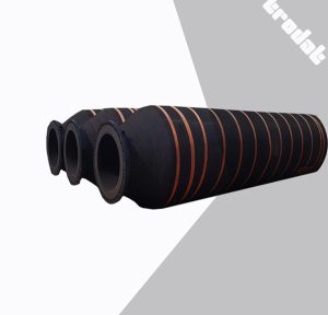
Rubber hose becomes valuable where the system must tolerate motion, vibration, and alignment drift. A typical dredging discharge rubber hose structure uses layered construction that combines rubber layers, fabric reinforcement, and steel wire reinforcement to handle pressure and mechanical loading.
Large-diameter suction and discharge hose designs are frequently specified with thickened wear-resistant inner rubber and reinforcement structures intended to handle suction and discharge duty cycles. In operation, the real advantage is not only pressure capability, but flexibility that keeps the line from fighting the vessel’s movement and the water’s motion.
Self-Floating Dredge Rubber Hose for Dynamic Water Conditions
A floating dredging pipeline section changes the design problem. The system is no longer only about hydraulics; it becomes a mechanical assembly exposed to surges, current, and cyclic bending.
Self-floating dredge rubber hose specifications often focus on abrasion-resistant outer layers, seawater corrosion resistance, a controlled bending angle range for working conditions, and flotation behavior defined by foam layers. In demanding installations, tensile strength ratings are also part of the selection conversation because towing and repositioning loads can exceed what many teams expect when weather turns.
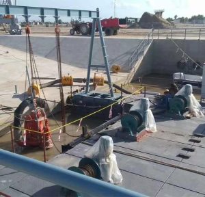
Floating Pipeline Behavior: Float Spacing, Routing, and Stress Control
Many jobsite disruptions begin with an unstable floating run. When float spacing is inconsistent, the line can sag and create low points where solids settle. When the route includes sharp direction changes, oscillation increases at the corners and concentrates stress.
A field-ready floating dredging pipeline design treats routing as a reliability tool. Gentle turns, controlled transitions, and predictable movement are the goal. If a line must cross a rougher section of water, the design should assume that motion will occur and provide controlled freedom of movement rather than rigid restraint.
The most expensive failures are often not blowouts in the middle of the line. They are fatigue failures at predictable stress points: near the stern transition, at shore crossings, or at interfaces where a rigid run meets a flexible section.
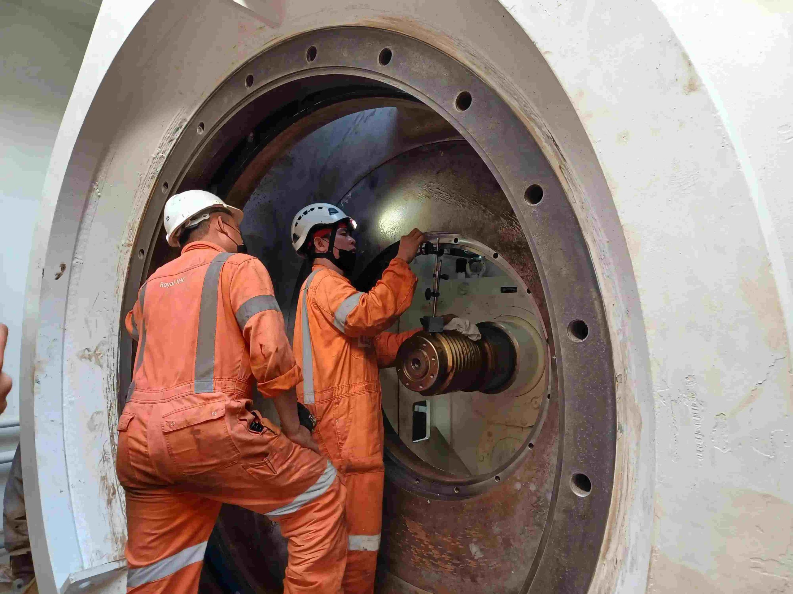
Connection Strategy: Ball Joints and Flanged Interfaces That Last
Connections are where uptime is won or lost. Leaks and misalignment tend to start at interfaces, then expand under vibration and pressure cycling.
Ball joints are commonly used to connect a steel discharge pipe at the stern to a floating rubber discharge hose on the water surface. The functional value is simple: controlled angular movement allows the pipeline to swing within a certain angle, accommodating expansion, bending, and vibration rather than forcing that movement into rigid flange faces.
A stable connection strategy also depends on installation discipline. Even strong hose and pipe can be undermined by poor alignment, torsion introduced during assembly, or inconsistent re-check practices once vibration has worked on the system for several shifts.
Commissioning That Prevents Week-Three Shutdowns
Commissioning is where a pipeline system reveals what the spreadsheet did not. A controlled ramp-up phase matters because slurry behavior is rarely constant. Early measurements should establish a baseline pressure profile, movement profile, and expected response when density increases.
When a system is pushed immediately to maximum production, small issues hide until they become expensive. A better approach is to run a controlled sequence: stable flow at lighter material, then incremental density increases while monitoring pressure stability and line behavior. If vibration concentrates at a bend, if a floating segment oscillates excessively, or if settling begins at a low point, it is cheaper to correct it early than to wait for a plug.
Troubleshooting: Plugging, Pressure Drops, Bursts, and Rapid Wear
Slurry pipeline plugging is rarely random. It tends to follow a pattern: velocity falls, solids begin to settle, head loss rises, flow drops further, and recovery becomes harder each minute. A safe response prioritizes restoring movement without creating pressure spikes that threaten a burst.
Sudden pressure drops often point to leakage or a coupling issue rather than a hydraulic change. Meanwhile, a steady pressure climb with declining discharge distance often points to increasing loss from settling, wear roughening, or unplanned routing changes.
Rapid wear tends to cluster at elbows and transitions. If a system shows repeat elbow failures, it is usually signaling a design mismatch: velocity too high for the geometry, too many tight turns, or a segment that should have been flexible but was built rigid.
Procurement Decision Judgment: What to Lock Down Before RFQ
Procurement teams get better outcomes when the RFQ package forces the right engineering questions early. The essential information is the expected discharge distance, route geometry, elevation changes, and the operating range for slurry density and particle behavior. For floating sections, the expected water conditions and movement exposure need to be explicit, because a calm-water assumption often leads to premature fatigue and unplanned replacements.
When the RFQ clarifies whether the system needs HDPE for long stable runs, discharge rubber hose for motion zones, and self-floating dredge rubber hose for dynamic water segments, suppliers can propose configurations that match real workflow rather than generic defaults.
For a deeper view on how pump selection interacts with slurry transport stability and discharge distance, refer to this resource: [dredging pump and slurry transport—designing systems that hold up on real job sites].
About TRODAT (SHANDONG) MARINE ENGINEERING CO., LTD
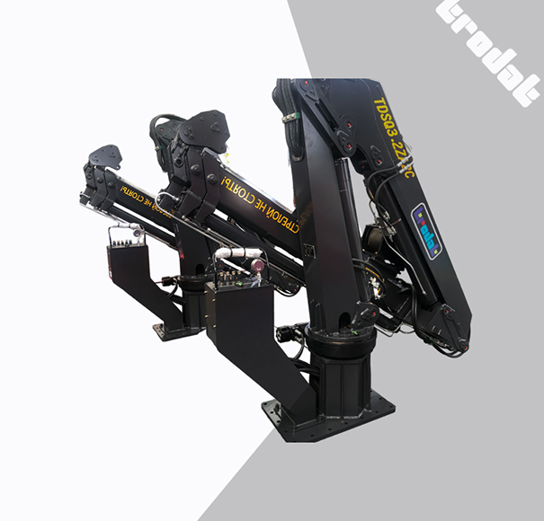
TRODAT (SHANDONG) MARINE ENGINEERING CO., LTD supplies dredging equipment and dredging parts intended for both newbuild dredgers and repair or maintenance needs on existing fleets. Its product scope covers dredging pumps, diesel engines, marine gearboxes, transfer cases, hydraulic pump stations, and dredging devices such as cutter heads and other excavating gear, along with deck machinery and outfitting used for mooring and towing. In slurry transport systems, the portfolio extends into suction and discharge pipeline system components, including discharge rubber hose, self-floating dredge rubber hose, and dredging-grade pipes and accessories.
The company states that production follows an ISO9001:2015 quality management system and that marine-use product certification support can be provided where required. That quality framework matters on pipeline projects because consistency in materials, reinforcement structures, and connection interfaces is what keeps performance repeatable across long shifts and rougher operating windows.
Conclusion
Reliable slurry transport does not come from a single “best” component. It comes from a pipeline system that matches the jobsite envelope, maintains a workable velocity window, and controls motion-related stress at the connections and floating segments. When dredging hose vs HDPE pipe choices are made by segment risk rather than habit, when floating pipeline routing limits oscillation, and when commissioning establishes a real baseline before production is pushed, pipeline interruptions become less frequent and easier to diagnose. For contractors and owners, that translates into steadier output, fewer emergency repairs, and more predictable project scheduling.
FAQs
What is the most common cause of slurry pipeline plugging on dredging projects?
Slurry pipeline plugging most often starts with settling in low points after velocity drops below a stable transport range. Once solids begin to accumulate, head loss rises, flow decreases further, and the system can enter a self-reinforcing cycle that ends in a blockage unless velocity is restored and the low point is addressed.
How should dredging hose vs HDPE pipe be decided for a discharge line?
The decision is usually strongest when made by segment. HDPE dredging pipe is a common choice for long, stable routes where alignment can be controlled and corrosion resistance is valued. Discharge rubber hose is often better near the dredger, at transitions, or in zones where motion and vibration are unavoidable and flexibility protects the system from fatigue and leakage.
How can discharge distance decrease in a slurry pipeline even when the pump is operating normally?
Discharge distance can drop when pipeline head loss increases beyond the original assumption. That often happens after routing changes add bends, when density swings increase friction loss, or when partial settling creates a rougher flow path. Rechecking the pipeline head loss calculation against field measurements is often the fastest way to separate pump limits from pipeline limits.
What does a ball joint do in a suction and discharge pipeline system?
A ball joint allows controlled angular movement between a stern discharge pipe and a floating hose section. By accommodating expansion, bending, and vibration, it reduces stress concentration at flange faces and can reduce leakage and fatigue failures in motion-heavy conditions.
How should float spacing be approached in a floating dredging pipeline?
Float spacing should be designed to prevent sagging that creates low points where solids can settle and to reduce oscillation that concentrates stress at interfaces. Stable routing and consistent support are typically more important than pushing the line to look “tight,” because controlled movement is safer than forced restraint in real water conditions.
Post Comment