


Pipeline design is where many dredging projects either stay on schedule—or quietly bleed productivity. In slurry transport, dredging pipeline diameter, length, and head loss are not academic terms; they set the ceiling on discharge distance, solids throughput, power demand, and wear rate. When the line is undersized or the routing is careless, crews often see the same symptoms: flow that looks fine at start-up, then drifts into unstable velocity, sanding, overheating, and repeated shutdowns to clear a plug.
Why these three variables decide real output
Diameter, length, and head loss are linked by a simple operational reality: every additional meter of pipe and every extra bend consumes energy. That energy must come from the pump as pressure. If the system cannot supply it with margin, the slurry slows down, solids begin to settle, and the pipeline turns into a restriction rather than a transport path.
A common failure pattern is “paper capacity versus site capacity.” A pump that appears adequate on a brochure can fall short once the pipeline includes a floating section, a shoreline transition, a land run with multiple elbows, and a lift to a discharge point. Minor losses and elevation losses stack up fast, and slurry behavior amplifies the penalty.
Head loss, in plain engineering terms
Head loss is a practical way to express pressure loss as “equivalent height of fluid.” The two buckets that matter in dredging are friction loss along straight runs and local losses caused by fittings and geometry.
Friction loss: the length penalty
For steady flow in a full pipe, friction loss is commonly modeled with the Darcy–Weisbach relationship, where loss rises with length, velocity squared, and friction factor—and falls with diameter.
Two implications show up immediately in dredging service:
First, long lines are not just “more pipe.” They create a larger energy sink that must be paid for every hour of the shift. Second, velocity is expensive. Raising velocity helps keep solids moving, but it increases friction loss sharply, which pushes the pump further from its best operating point.
Minor losses: bends, reducers, and “small” mistakes that are not small
Elbows, tees, reducers, valves, and entry/exit transitions create local losses that can be expressed as an equivalent length of straight pipe. In high-volume dredging, a small collection of fittings can act like dozens—or hundreds—of meters of extra pipe, especially when velocity is high.
This is why routing discipline matters. A line that looks compact on a site sketch can be hydraulically longer than a cleaner layout with fewer direction changes.
Elevation head: the vertical tax
If discharge must climb, static head adds directly to required pressure. That makes elevation one of the most “non-negotiable” contributors to head loss. Unlike friction losses, there is no diameter adjustment that makes elevation disappear; it can only be reduced by changing discharge point, staging booster systems, or rethinking where solids are placed.
Diameter trade-offs: why “bigger” is not always better
Pipeline diameter is often treated as a one-step answer: go larger and problems go away. In dredging slurry service, the choice is more nuanced because diameter changes velocity, deposition risk, wear patterns, and the practical handling of pipe and hoses.
Velocity, deposition, and the plug that arrives slowly
If velocity drops too low, solids begin to settle and form a bed. Once the bed forms, pressure rises, flow becomes unstable, and a full blockage can follow. Literature commonly frames this as staying above a deposition or critical velocity threshold, which depends on particle size distribution, solids concentration, fluid rheology, and pipe geometry.
A larger diameter can reduce friction loss for a given flow rate, but it also lowers velocity unless flow increases. That can raise deposition risk in long horizontal sections. On many sites, the “safe” solution is not simply larger diameter; it is a diameter-and-flow pairing that preserves transport velocity without driving head loss beyond pump capability.
Wear and operating cost: velocity is a double-edged tool
Higher velocity helps keep solids suspended, but it can accelerate abrasion, especially at elbows and transitions. A design that relies on “velocity brute force” may clear well for a short period, then degrade quickly through thinning, leaks, and frequent repairs. This is where material choice and fitting strategy become part of hydraulic design, not a separate purchasing exercise.
Length is not just distance: layout choices that change system behavior
Dredging pipelines are rarely a single straight run. They are a chain of environments: dredger connection, floating line, shore approach, land line, and discharge geometry. Each segment introduces different mechanical and hydraulic constraints.
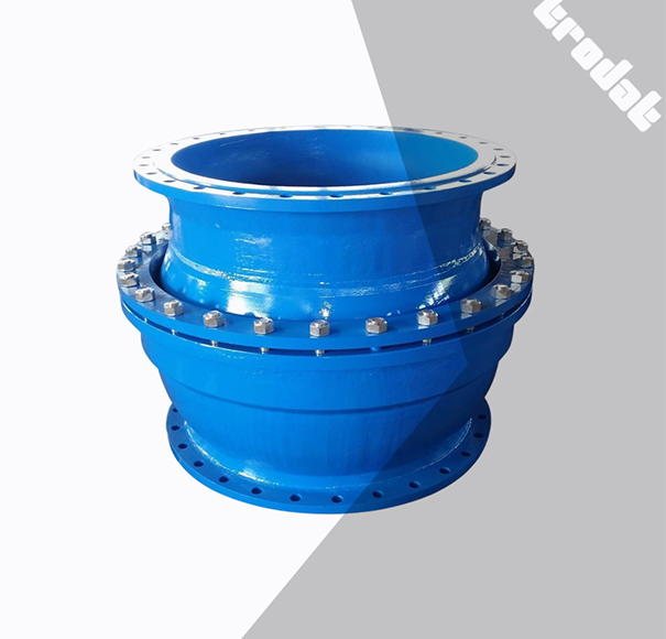
One overlooked factor is how joints and transitions handle movement. For example, in discharge systems a ball joint is used to connect the stern steel discharge pipe to a floating rubber discharge hose, allowing controlled swing and accommodating expansion, bending, and vibration.
That flexibility can protect the line mechanically, but every transition still needs hydraulic attention—especially if the internal profile creates turbulence or contraction.
A practical sizing workflow that matches job-site reality
Sizing becomes manageable when it follows field constraints rather than ideal assumptions.
Start with the production target, then convert to slurry flow
Production is usually specified as solids volume per hour or in-place excavation output. Transport design needs slurry flow rate at the pipeline, which depends on target solids concentration by volume and the density relationship between water and solids. If the job requires high solids concentration, the pipeline must be designed for higher mixture density and potentially different rheology.
Select a transport velocity range that is stable, not heroic
The goal is a velocity that resists deposition while keeping pressure and wear within reasonable limits. In coarse or mixed gradation material, the velocity requirement can rise, but raising velocity blindly is a common reason head loss runs away. Use the site’s real material profile—fine silt behaves differently than sand and gravel, and “slurry” is not a single fluid.
Estimate total head loss with conservative geometry, then add margin
Compute straight-run friction losses, then include fitting losses and elevation. Build the model using the real count of elbows, reducers, valves, and transitions. If the discharge location is likely to change during the season, incorporate the worst-case routing early to avoid redesign mid-project.
At this stage, it helps to align pipeline assumptions with pump and system selection logic. A pipeline is not independent from the pump curve; it defines where the pump will operate. For a broader view of how pumps, losses, and wear trade against each other, refer to Dredging Pump and Slurry Transport: Designing Systems That Hold Up on Real Job Sites.
Iterate diameter and layout as a system decision
If total head is too high, the response is not always “bigger pipe.” Sometimes a cleaner route with fewer high-loss fittings yields more benefit than a diameter change. In other cases, segmenting the line—floating versus land—using different materials or diameters can stabilize both hydraulics and handling.
Common failure modes and how to prevent them
“Discharge distance not reached”
This typically shows up when friction and minor losses exceed expectations or when the pipeline includes more elevation than planned. The corrective action is usually a combination of improved routing discipline, revisiting diameter for velocity stability, and aligning the pump operating point with the true system curve.
Plugging after a few hours: the slow-developing blockage
A pipeline that plugs late in the shift often has a velocity problem, not a one-time obstruction. The bed forms gradually in a long horizontal run or in a low-velocity dead zone near transitions. Prevention is largely about keeping the system in a stable regime: steady flow, controlled concentration, and avoiding long idle periods with solids in the line.
Leaks and premature wear: hydraulics meet installation discipline
Hydraulic design sets the pressure environment; installation quality determines whether the line survives it. In dredging discharge service, flange rubber hoses are typically built with layered reinforcement—inner rubber layer, cord fabric layers, steel wire reinforcement, and weather-resistant outer rubber—designed for abrasion and pressure cycling.
When leaks occur early, the root cause is often misalignment at flanges, poor support, uncontrolled bending at transitions, or repeated torsion at joints. Tight geometry and rapid schedule pressure can lead crews to “make it fit,” which becomes expensive once wear and leaks start. The fix is not only better hose selection; it is enforcing alignment, restraint, and support geometry during installation.
Matching pipeline materials to dredging phases and site constraints
Material choice is where B2B buyers can make the system either forgiving or fragile.
Floating sections: buoyancy and motion control
Floating hoses are often selected when the pipeline must ride waves and maintain a controlled float profile. TRODAT describes self-floating hoses as suitable for harsh sea or mining conditions, using a PE foam body adjusted to slurry buoyancy and offering inner diameters up to 1200 mm across lengths and pressure ranges.
In internal documentation, self-floating dredge rubber hoses are also framed as being used under surge impact, with structural features such as an independent foam floating layer and stated bending angle range.
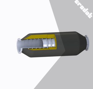
When floating lines are part of the design, the operational priority is steadiness: maintaining flow without oscillation-driven fatigue and without creating internal turbulence at couplers and transitions. The right product is the one that matches the sea state, bend requirements, and connection strategy—not the one with the most aggressive headline spec.
Product reference for that segment can point directly to floating dredging hoses.
Land and underwater runs: durability, handling, and long service life
For long land runs and certain underwater placements, HDPE is frequently considered because it is durable, corrosion resistant, and practical to handle at scale. TRODAT positions HDPE dredge pipe for dredging and water-mining pipelines as well as municipal water supply and drainage uses, and notes broad service applications including slurry transport.
Internal material also highlights long service life claims under normal conditions and corrosion resistance benefits.
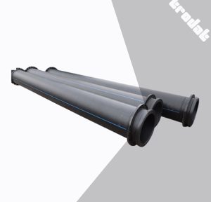
For projects that need frequent reconfiguration, handling logistics and jointing method matter just as much as the nominal pressure rating. A line that cannot be moved, supported, and maintained efficiently becomes a schedule risk.
Relevant product reference: HDPE dredge pipe.
Procurement decisions: what should be clarified before quoting
For buyers, the highest-risk mistake is requesting a quote without pinning down the operating envelope. Pipeline suppliers and system integrators can only size responsibly when they know the real slurry profile, target concentration, discharge distance, elevation changes, number of fittings, expected sea state for floating sections, and the expected duty cycle.
It is also worth requiring that the proposal describes how the system will be installed and supported, not only what will be delivered. Many cost overruns come from mismatched assumptions about site assembly time, jointing approach, and maintenance access once the line is live.
About TRODAT (SHANDONG) MARINE ENGINEERING CO., LTD.
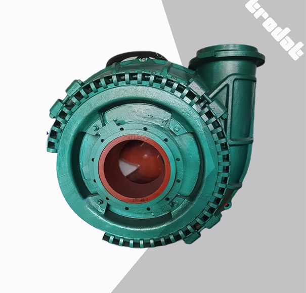
Dredging contractors and project owners often prefer suppliers that can think in systems rather than single components, because pipeline sizing decisions touch pump selection, wear behavior, and operational continuity. TRODAT (SHANDONG) MARINE ENGINEERING CO., LTD presents itself as a professional supplier of dredging equipment and parts for new-build dredgers and maintenance of existing units, with a product range spanning dredging pumps, dredging devices, deck machinery, and pipeline systems.
The company also states that production follows ISO9001:2015 and that IACS product certification for marine use can be provided—an important signal for buyers who need repeatability, documentation, and predictable performance under harsh field conditions.
Conclusion
Diameter, length, and head loss are the three knobs that decide whether slurry transport behaves like a controlled process or a daily firefight. A defensible design keeps velocity stable enough to avoid deposition, limits avoidable losses through disciplined routing, and selects materials that tolerate the real mix of abrasion, motion, and pressure cycling. When those decisions are made as a system—pipeline, fittings, transitions, and pump working point together—projects gain the two outcomes B2B operators value most: predictable production and fewer stoppages.
FAQs
What is the fastest way to estimate head loss for a dredging pipeline?
A fast first pass is to estimate friction loss with a Darcy–Weisbach approach for straight runs, then add fitting losses and elevation head. Even in early estimating, the geometry count and elevation are often more decisive than fine-tuning friction factor.
Does a larger pipeline diameter always reduce head loss in dredging?
It often reduces friction loss for a given flow rate, but it can also lower velocity and raise deposition risk if flow does not increase. Diameter selection should be paired with a velocity target that keeps solids moving while staying within pump capability and wear limits.
How can plugging risk be reduced in long discharge lines?
Plugging risk typically drops when velocity stays above the deposition threshold, dead zones are removed from routing, and idle periods with solids in the pipe are minimized. If the line must stop, controlled flushing procedures and restart planning can be as important as the original diameter choice.
When is HDPE dredge pipe a better choice than floating hoses?
HDPE dredge pipe can be a strong fit for long land runs and many underwater applications where durability, corrosion resistance, and handling logistics dominate. Floating hoses are typically selected when buoyancy and wave-driven movement are primary constraints.
Post Comment